This post explains how to increase the number of controllable signals of a model railway from iTrain in an economical way, with an approximate cost of 0.7€/output using DCC-EX.
I control the locomotives and turnouts with the ROCO Z21 application or from iTrain. The problem is that to control traffic signals and building lights to create animations with Z21, I need a Z21 switch DECODER (10836) which costs around 80€ for 8 independent digital outputs (8 two-color signals), 10€/output. iTrain allows having two controllers and, therefore, I can add an EX-CommandStation (EX-CS) to control signals and lights while keeping the Z21 for the rest of the functionalities. An EX-Command Station without DCC output (an Arduino MEGA) has an approximate cost of 22€ and, in a simple way, you get about 32 independent outputs (0.7€/output).
Basic EX-CommandStation
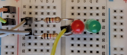
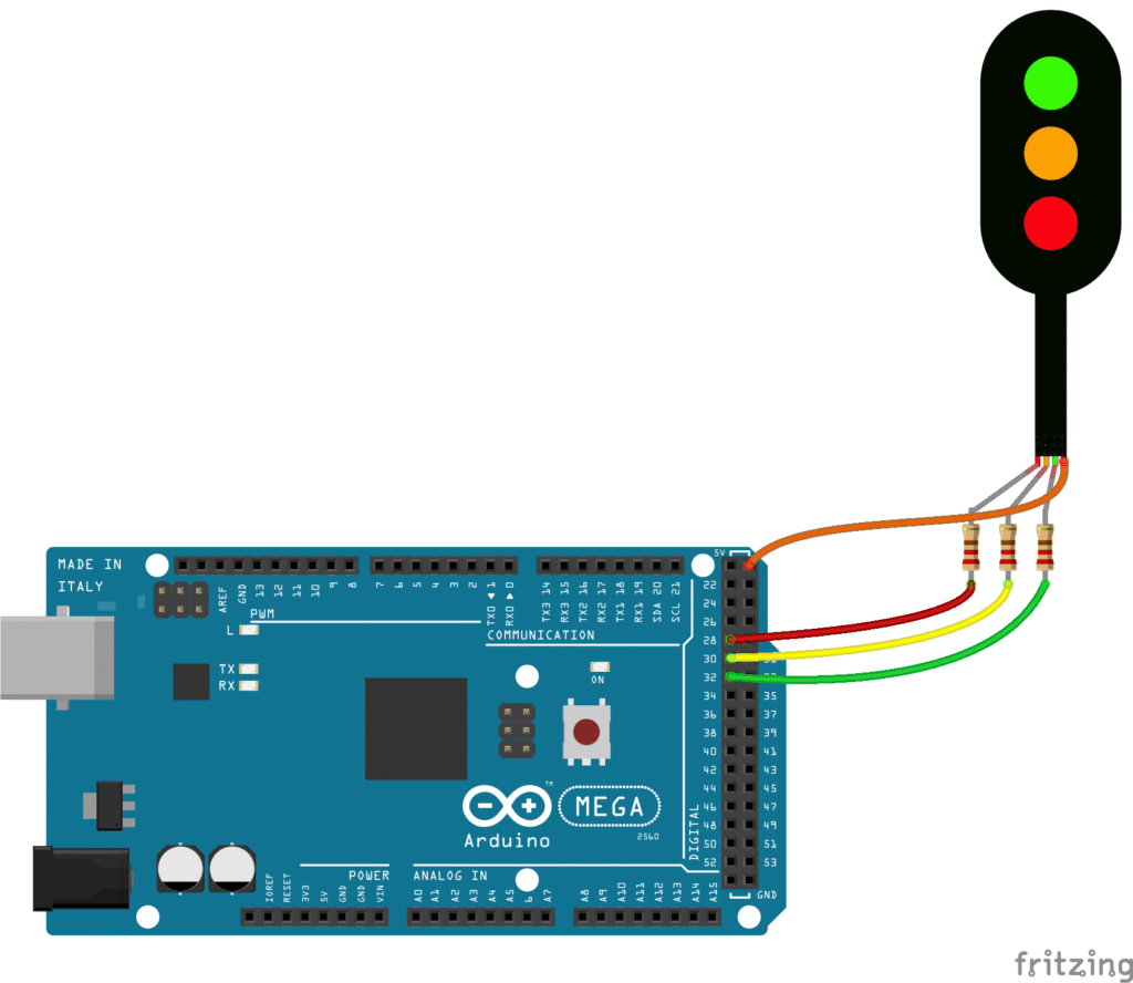
To control lights we need an EX-Command Station (it does not need the motor shield), therefore only an Arduino MEGA is needed. The first step is to make sure that we can control the LEDs from the EX-CS. Using the connections from the documentation (Active Low Signals) and the attached configuration file, we can check, using the web controller, that when activating animation “1” the two LEDs blink. Loading a configuration file is easy using the official EX-Installer.
// myAutomation.h - Generated by EX-Installer v0.0.20 for EX-CommandStation v5.4.18-Prod

AUTOSTART
POWERON
DONE

// ==============
// SINGALS
// ==============
SIGNAL(28,0,30) // ID is 28

// ==============
// AUTOMATIONS Verification of SETUP
// ==============
AUTOMATION(1,"Red and Green")
GREEN(28)
DELAY(1500)
RED(28)
DELAY(1500)
DONE

// ==============
// MAP OF DCC ACCESSORY TO DCC-EX Signal (Easier to maintain) OPTION A
// ==============
ONACTIVATEL(60)
  GREEN(28)
DONE

ONDEACTIVATEL(60)
  RED(28)
DONE

// ==============
// MAP OF DCC ACCESSORY TO DCC-EX PINS (no need to define signals) OPTION B
// ==============
ONACTIVATEL(61)
  SET(28)
  RESET(30)
DONE

ONDEACTIVATEL(61)
  RESET(28)
  SET(30)
DONE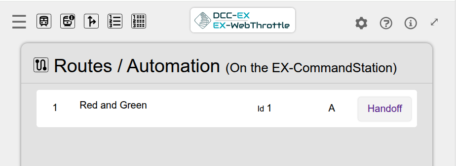
How to integrate with iTrain
iTrain cannot send commands to the EX-CS to turn on lights using the DCC-EX signal identifiers. iTrain can send commands to DCC accessory addresses and, therefore, EX-CS must be made to turn on the lights when receiving these commands. For example, these lines make it so that when activating/deactivating the accessory with address 60 (which does not exist), the signal is set to green/red.
ONACTIVATEL(60) // When receiving DCC-Accessory Addres 60 to HIGH
  GREEN(28)     // Then turn green signal 28
DONE
ONDEACTIVATEL(60)
  RED(28)
DONE
The explained option A is the simplest one I have found. Option B is to directly configure the pins. It is more flexible, as it allows having multiple LEDs turned on in different states.
NOTE regarding consumption: Using small warm LEDs and a 1k Ohm resistor, the approximate consumption is about 2mA and, therefore, it can perfectly support 32 independent LEDs connected directly to the Arduino. In the case that the consumption increases a lot, it can be reduced by having the output control an optocoupler connected to an independent power supply.